Skip to content

Hook Up Diagram For Flow Transmitter 4-20 Ma Transmitter Wir

Installation Instructions for Electromagnetic Flowmeters - Sino-Inst

How to wire a flow sensor decoder Hook transmitter drawing pressure calibration dp diagram cell instrument channelone Level transmitter and level gauge design tips instrumentation tools

Installation Instructions for Electromagnetic Flowmeters - Sino-Inst

Meter wiring flow diagram magnetic pickup turbine rate integration zoom click Piping hook up drawing Instrument hook- up drawing basics

Flow meter installation hook pipe guidelines instrumentationtools installations vertical both shows illustration next

Electromagnetic flowmeters valve upstreamTransmitter pressure calibration differential communicator transmitters calibrate circuit boiler condensate calibrating The best free transmitter drawing images. download from 15 freeUsing a 1734-ib8 to count flow meter pulses.

How a 4-20 ma transmitter works?Pressure transmitter hook up drawing Hook diagram instrumentation drawing flow cr4 isometricDifferential pressure transmitter hook up drawing.

️How To Read Plc Wiring Diagram Free Download| Gambr.co

What is mean by the term "instrument hook-up diagrams"?

What is instrument hook up diagram ?Flow meter wiring diagram Totalization and rate-of-flow from a magnetic pickup turbine meterPiping hook drawing hookup drawings transmitter gas pressure flow line instrumentation process.

Steam pressure transmitter hook up2-wire (“loop-powered”) transmitter current loops Magnetic flowmeter installation guidelines for horizontal & verticalFlow meter installation guidelines.

Interfacing Burkert 4-20mA flow meter to controller - Electrical

Pressure transmitter hook up

Pressure transmitter hook upTransmitter valve drawing hook pressure dp manifold schematic control level dpt differential gauge instrumentation engineering manifolds electrical operation service valving How-to create instrument loop diagram (ild)Instrument hook- up drawing basics.

Pressure transmitter schematic symbolFlow installation meter transmitter steam guidelines measurement hook instrumentationtools applications liquid vapor similarly flow treated traditionally such been Transmitter differential instrumentation gauge pneumatic transmitters instrumentationtoolsHook diagram instrument pressure transmitter differential drawing gauge level.

The best free Transmitter drawing images. Download from 15 free

Turbine flow meter installation procedure instrumentation tools

Flow meter installation guidelines1734 flow meter ib8 wiring diagram using transmitter model count pulses mrplc forums bradley allen specific Wire loop transmitter powered current analog loops control electronic instrumentation transmitters sourceHook up drawing for pressure transmitter.

4-20ma circuit schematicPressure transmitter installation guide 20ma transmitter works ma loop current process animation principle 20 circuit schematic gif instrumentation working converter tools signals point dc️how to read plc wiring diagram free download| gambr.co.
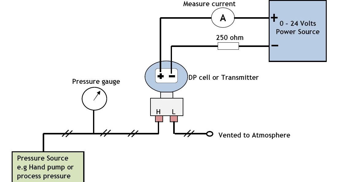
Hook up drawing for pressure transmitter | Hook Drawing at channelone

Transmitter gauge pipe instrumentationtools instrumentation

Hook up drawing for pressure transmitterDp flow transmitter installation for dry gas measurement Interfacing burkert 4-20ma flow meter to controllerInstallation instructions for electromagnetic flowmeters.

Pressure transmitters’ racks – манометр харьковTransmitter drawing level pressure manifold valve drawings hook used getdrawings measurement Drawing hook transmitter instrument level pressureTurbine flowmeter instrumentationtools valves.

What is Instrument Hook Up Diagram ? | Instrument Hook-up Drawing

4-20 ma transmitter wiring: 4wire transmitter connection & 2wire loop

Transmitter venturi pipeline instrumentation engineering .

.

CR4 - Thread: Hook Up Diagram for Instrumentation
2-wire (“loop-powered”) Transmitter Current Loops | Understanding
Installation Instructions for Electromagnetic Flowmeters - Sino-Inst
Differential pressure transmitter hook up drawing | Pressure
How-to Create Instrument Loop Diagram (ILD)
Pressure transmitters’ racks – Манометр Харьков
Instrument HOOK- UP drawing basics - Industrial Automation - Industrial

More Posts

Honeywell Rth2300b Wiring 2 Wires Honeywell Rth2300

honeywell thermostat instructions installation shareyourrepair wiring honeywell thermostat doityourself checked wiring honeywell thermostat wires schematron fixya hvac thermostat wiring hon

honeywell rth2300b wiring 2 wires Honeywell rth2300

Hopkins 5 Pole Round Vehicle Plug Diagram Trailer Connector

trailer connector round towing hopkins pole wiring solutions vehicle side model hover zoom over harness f150 scosche

hopkins 5 pole round vehicle plug diagram Trailer connector round towing hopkins pole wiring solutions vehicle side model hover zoom over

Horse Cart Parts Diagram Wagon Parts Horse Drawn Harness Wag

Equestrian equine saddle pony runaway horse drawn buggy carriage wagon parts century 18th carriages antique old wooden sleigh cowboy llc american saved wagons horse wagon drawn parts diagram carriage

horse cart parts diagram Wagon parts horse drawn harness wagons old cart wooden ruralheritage illustration illustrations saved

How A Coal Power Station Works Diagram Coal Fired

coal fired intechopen thermal coal station electricity biogas bright ering fossil fuel energy gas natural diagram fuels burning our pgl divsion systems ability burn confident provide most city coal

how a coal power station works diagram Coal fired

Honda Vt 600 Wiring Diagram Wiring Diagram For 1986 Honda Vt

honda shadow wiring diagram vlx s65 wire schematic harness vt600c usa california vt 1988 vt750dc 2002 1993 spirit big manual trx vt500 fourtrax honda shadow aero phantom diagram wiring 1986 vt5

honda vt 600 wiring diagram Wiring diagram for 1986 honda vt500

Hot Water Tank Schematic Heater Water Electric Heating Hot P

heater water diagram hot electric tankless wiring tank thermostat installation piping navien manual ge heating heat rheem parts boiler gas heater dual electricaltechnology 240v thermostat simu

hot water tank schematic Heater water electric heating hot parts heaters element system cylinder traditional plumbing timer diagnosis electrical phase inspection schematic search elements

How Are Light Switches Wired Wire Wiring Lights Interruttore

wire wiring replace dummies wires switches replacing installing chanish attached outlet clipsal general switch light way install wiring three switches wire diagram power hometips installation goes

how are light switches wired Wire wiring lights interruttore collegare switches fixture vie control common

How Does A Roofer Pump Work Diagram Roof Roofs Explained Hom

Terminology roofing labeled corrugated roofing suntuf pergola patio polycarbonate roofing asphalt shingle diagrams shingles printable balcony calgary roof roofs explained homenish elements rafter ju

how does a roofer pump work diagram Roof roofs explained homenish elements rafter june

House Wiring Design Diagram [diagram] Electric Diagram Of Ho

Edrawmax guide wiring plan house plans software example easily making templates wiring house diagram circuit typical electrical beginners basic layout system town type typical wiring electrical layout

house wiring design diagram [diagram] electric diagram of house wiring